A. Procedure of Dynamic Testing
1. The test pile shall be installed using approved installation procedures.2. Drill 2 8mm diameter clearance holes at the distance about 2-3 times piles section size below the top level. The hole must be in opposite side one to another.3. Gauges shall be attached in a secure manner as to prevent slippage under impact using bolts and nut mechanism.4. Apply plywood cushion to the top pile5. At least two hammer impacts should be applied to the top pile. First drop height should be minimal to allow the testing personnel to assess the testing equipment, the driving system and the pile stresses.6. Subsequent impacts can then be applied by utilizing higher drop heights7. Upon completion of the test, the pile can be returned to acceptable production condition.
B.
Reporting
of Result
The
PDA engineering report primarily covers the field results and results from
CAPWAP analysis (Case Pile Wave Analysis Program).
Field
reports generated are:
1. Maximum
measured force
2. Maximum
calculated tension force
3. Transferred
energy
4. Corresponding
stresses
5. Bearing
Capacity using Case Method
CAPWAP
Analysis reports generated are:
1. Pile’s
estimated static capacity and it’s distribution along shaft and the toe
2. Pile’s
dynamic response (damping and stiffness).

Figure 1. Schematic of PDA Test
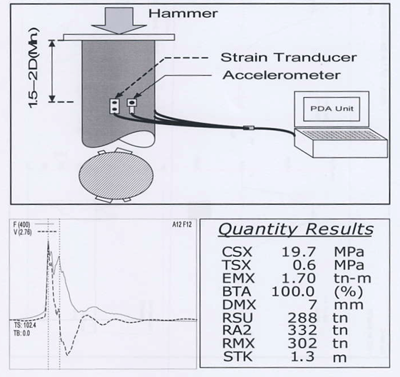 |
Figure 1. Schematic of PDA Test and Out Put